|
A POV Scene Explained Step by Step
I don't intend to provide a POV user guide. You will
have to learn the POV syntax by yourself if you want to add fancy textures
on your molecules. However, I will explain a typical POV scene generated
by the Swiss-PdbViewer. Usually, the image generated by POV will be very
close to the one you can see with the QuickDraw3D preview. The only thing
you will probably have to adjust is the distance between the camera and
the model.
First of all, a syntax definition: // at the beginning of a line
means that it will be ignored by POV. To comment a block of lines, put
a /* before the first caracter to ignores and a */ after the last caracter
to ignore.
Now, let's look step by step at the scene description:
//
// POV-Ray ray tracer scene file, generated by Swiss-PdbViewer
// File:1crn*.pov
// Swiss-PdbViewer can be retrieved by anonymous ftp at:
// http://www.expasy.ch/spdbv/../mainpage.htm
//
// POV-Ray can be retrieved at: http://www.povray.org
// N.Guex, 1995/96
//
#version 2    // this scene uses POV-Ray 2.x syntax

#include "colors.inc"
#include "textures.inc"
Includes colors, shapes and textures definitions.
// ------ COLORS ---------
#declare ATM_FINISH = finish {specular 1 roughness 0.001}
Defines the finish (aspect) of atoms. This is "Shiny", but you
could change these values to get something metallic.
#declare Surf_tex = texture { pigment { colour red 0.500 green 0.500 blue 0.500 filter 0.000} finish{ metallic }}
#declare N_tex = texture { pigment { colour red 0.240 green 0.320 blue 1.000 } finish{ ATM_FINISH }}
#declare C_tex = texture { pigment { colour red 1.000 green 1.000 blue 1.000 } finish{ ATM_FINISH }}
#declare O_tex = texture { pigment { colour red 1.000 green 0.000 blue 0.000 } finish{ ATM_FINISH }}
#declare P_tex = texture { pigment { colour red 1.000 green 0.660 blue 0.090 } finish{ ATM_FINISH }}
#declare H_tex = texture { pigment { colour red 0.300 green 0.800 blue 1.000 } finish{ ATM_FINISH }}
#declare S_tex = texture { pigment { colour red 1.000 green 0.940 blue 0.000 } finish{ ATM_FINISH }}
#declare X_tex = texture { pigment { colour red 0.625 green 0.625 blue 0.625 } finish{ ATM_FINISH }}
#declare SS_Bnd_tex = texture { pigment { colour red 1.000 green 0.940 blue 0.000 } finish{ ATM_FINISH }}
#declare Strong_HBnd_tex = texture { pigment { colour red 0.000 green 1.000 blue 0.000 filter 0.5} finish{ ATM_FINISH }}
#declare Weak_HBnd_tex = texture { pigment { colour red 0.562 green 0.687 blue 0.562 filter 0.5} finish{ ATM_FINISH }}
Define rgb colors for GRASP surfaces, atoms and H-bond. Note that
the "filter" value present for some colors defines the transparency from
0 (solid) to 1 (completely transparent).
#declare r_Atm = 0.200   // atom radius
#declare r_Bnd = 0.200   // bond radius
#declare r_HBnd = 0.075   // H-bond radius
All these numbers are in Angstroms. By default, atom radius is
equals to bond radius. It allows to generate smooth "sticks"
models. Note that all these radii can be modified directly from within
Swiss-PdbViewer.
// ---- Radius for "spacefilled" atoms ----
 #declare rO_ = 1.4
 #declare rN_ = 1.5
 #declare rC_ = 1.7
 #declare rS_ = 1.85
 #declare rP_ = 1.9
 #declare rH_ = 1.1
 #declare rX_ = 1.0
The previous section assign radii for "space
filled" atoms.
Note that atoms are rendered as "Spacefilled" only when the column "dot
surface" of the control Panel is checked.
It allows you to render very easily models in "mixed
mode".
// ---- Radius for "joining" atoms ----
 #declare VDW_factor = 0.200   // changing this value will alter the
                                  radius of "joining" atoms

// when atom radii below are all set to 1.0, you obtain
                                a smooth "sticks" model
 #declare rO = 1.0 * VDW_factor
 #declare rN = 1.0 * VDW_factor
 #declare rC = 1.0 * VDW_factor
 #declare rS = 1.0 * VDW_factor
 #declare rP = 1.0 * VDW_factor
 #declare rH = 1.0 * VDW_factor
 #declare rX = 1.0 * VDW_factor
The previous section assigns the radii for the atoms (spheres)
that will be joined by the bonds. Obviously, in the case demonstrated
here, you won't see them. However, you could modify these values to obtain
a "balls & sticks" model.
// ---- some TEXT parameters ----
 #declare Label_scale = .75   // Text height in angstroms
 #declare Label_XDecal = .6 // Horizontal offset from CA
 #declare Label_YDecal =  -.5 // Vertical offset from CA

 #declare Dist_scale = .5   // Text height in angstroms
 #declare Dist_XDecal = -.3 // Horizontal offset from middle of H-bond
 #declare Dist_YDecal =  0  // Vertical offset from middle of H-bond

#declare Label_tex = texture { pigment { colour red 1.000 green 1.000
                                         blue 1.000} finish{ metallic }}
#declare Label_tex = texture { pigment { colour red 1.000 green 1.000
                                         blue 0.000} finish{ metallic }}
The previous section defines some parameters (such as label placement
and color) that will be used to place "solid
3D text" that will be rendered along with your image (available only
with POV3).
//************ OBJECTS *********
#include "molcolor.inc"
#include "asphis.inc"
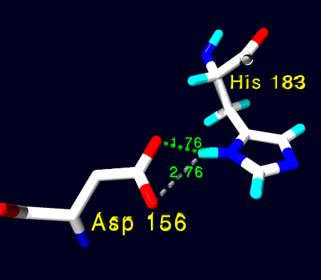
object{ A0_shape } // ASP156
text{ttf "cyrvetic.ttf", "Asp 156",.5,0.1*x
texture{Label_tex} scale
translate <-3.625+Label_XDecal,-3.279+Label_YDecal,-1.095>}
object{ A1_shape } // HIS183
text{ttf "cyrvetic.ttf", "His 183",.5,0.1*x
texture{Label_tex} scale
translate <1.340+Label_XDecal,1.641+Label_YDecal,1.434>}
object{ Hbnds }
The first include get the atoms colors definitions. You can edit
this file to change the default atoms colors, H-bond colors and so on.
This file must reside either in the same
folder as the .pov and .inc files you want to render, or in the folder
where all other includes files (colors.inc, textures.inc and so on...)
reside.
The next line calls the molecule atoms and bonds definitions. The next
bunch of lines call each groups If you want to remove just one amino-acid
from the final rendering, you will just have to put // in front of the
object you want to remove.
As you may notice, the three lines slightly decaled onto the right define
"solid 3D text" that will be rendered
along with your image (available only with POV3). You will probably
need to modify the position of some labels to insure they are visible.
//************ CAMERA *********

camera { location < 0, 0, -15.727>  // get closer to <0,0,0> to
                                             zoom in on the model
// rotate < 0, 2.000, 0>    //  uncomment to get  left Eye stereo view
// rotate < 0, -2.000, 0>   //  uncomment to get right Eye stereo view
 direction < 0, 0, 1.207>
 up <0, 1, 0>
 right <100/100, 0, 0>  // **NOTE:** do not forget to adjust this value
                                 according to final Width/Height rendering
 look_at <0, 0, 0>
}
This section defines the camera position and direction. You may
have to change the last term of the "location" part. Increasing it will
put the camera closer to the model, and so it will appear enlarged.
The "right" term difines the width/height ratio. Its default value is
1, meaning that you will have to render squared images in order to observe
no distortion. If you change the image size to 640 by 480 pixels, do not
forget to modify the first term by 640/480 = 1.333333
Note: if you want to render the left or right part of a stereo view, simply
uncomment the appropriate "rotate" command. Only one of the two "rotate"
should be uncommented at the same time.
Note that you can specify which image has to be calculated directly from
within Swiss-PdbViewer, as the parameters set in the QuickDraw3D preference
dialog will be taken into account.
//************ LIGHTS *********

#declare Intensity = 2
background { color rgb <0.000,0.000,0.125> }
object { light_source {<-20.000,20.000,-20.000> color rgb Intensity*1.000 }}
object { light_source {<0,0,-200.000> color rgb Intensity*0.7 }}
Obviously, here are the light sources. You may have to move their
locations to get nice results, but it usually works like that. The more
light sources you put, the longer it takes to render the scene.
Note that you can modify the position and intensity of the light sources
directly from within Swiss-PdbViewer.
|
 ExPASy Home page